- Introduction
- Hardware
- Software
- Flashing IPFire image
- OS Configuration
- Enabling Wireless Access
- IPFire Web interface
- OpenVPN
- Adding a firewall rule in the Gateway VM
Introduction
Post Malware Analysis Lab - Part 1 - The Gateway, details the steps taken to create a “Gateway” virtual machine hat can be used on a Malware Analysis environment.
A Raspberry Pi computer board allied with IPFire Operating System can be used to extend the environment capabilities to include Router, Firewall and OpenVPN client capabilities.
For more information about what a Router can do with the network, please see Laura Chappel’s YouTube video here.
Logical architecture
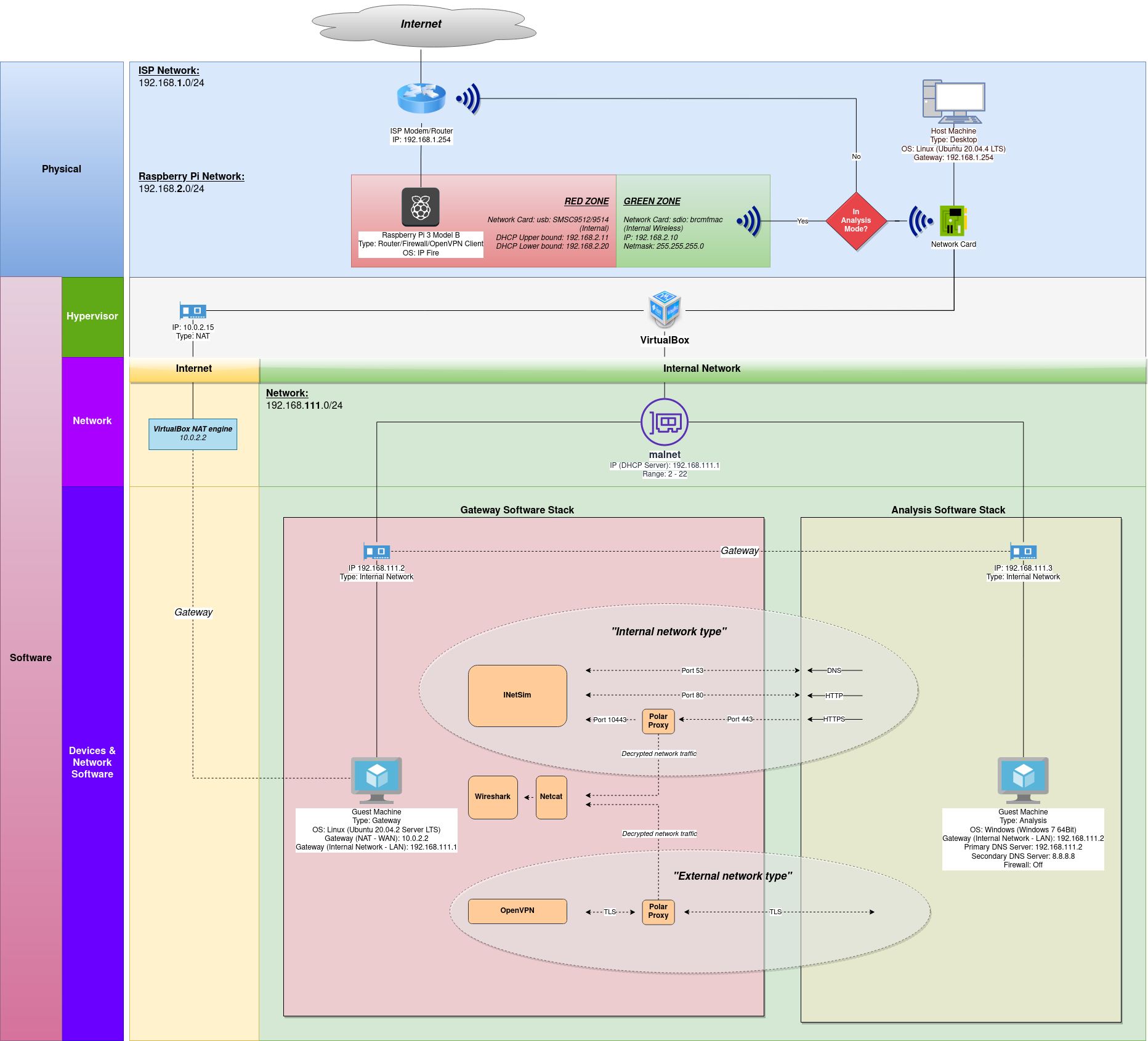
The following image shows the logical architecture of the lab environment. Changes to the environment are at the top of the image in the “Physical” layer of the diagram. Every other aspect of the environment is unchanged:
Hardware
Please note that a Raspberry Pi computer board is required to follow the instructions in this post.
Software
IPFire will be used as the Operating System. For more information about which Raspberry Pi versions are supported by IPFire, please see this link: https://wiki.ipfire.org/hardware/arm/rpi
“IPFire is a hardened, versatile, state-of-the-art Open Source firewall based on Linux. Its ease of use, high performance in any scenario and extensibility make it usable for everyone.” IPFire website
Download the OS image for the Raspberry Pi model used from https://www.ipfire.org/.
Flashing IPFire image
When the download finishes, flash the downloaded image to an SD Card. If using Linux, the following commands can be run to flash the image to the SD Card (IPFire website provides instructions for other Operating Systems):
-
lsblkshows the devices currently mounted and can be used to identify the SD Card,
-
umount /dev/sdXunmount the “sdX” (SD Card) drive partitions,
-
xzcat /path/to/IPFIRE_IMAGE.img.xz | sudo dd bs=1M of=/dev/sdXwrites the “IPFIRE_IMAGE” image located in the absolute path “/path/to” to device “X”,
-
In my case I had to edit the “uENV.txt” file and change “SERIAL-CONSOLE” from “ON” to “OFF” to enable HDMI output and USB keyboard,
-
eject /dev/sdXunmounts and ejects the “sdX” drive from the computer.
When the process finishes, the SD Card can then be removed from the computer.
OS Configuration
Plug the SD Card in the Raspberry Pi, connect the Raspberry Pi to your ISP modem and connect the Raspberry Pi to a power source. Wait a couple of minutes for the Operating System to boot. IPFire comes with a handy setup tool to guide through the initial configuration process.
The first screen allows to choose the “Keyboard” map to use, the next screen selects the “Timezone”, followed by “Hostname” and “Domain name” setup screens.
The installation process then goes through setting the root user password for access to the Raspberry Pi box, followed by the admin user password, required for access to the web interface.
Unfortunately, I didn’t take pictures of the configuration screens when I was configuring my system. The following images were taken after the configuration using a SSH remote connection to capture the configuration details.
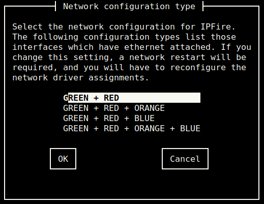
In the “Network configuration menu” select “Network configuration type” and make sure to use “GREEN + RED”. The Raspberry Pi has 2 network cards out of the box, we can only create 2 network interfaces.
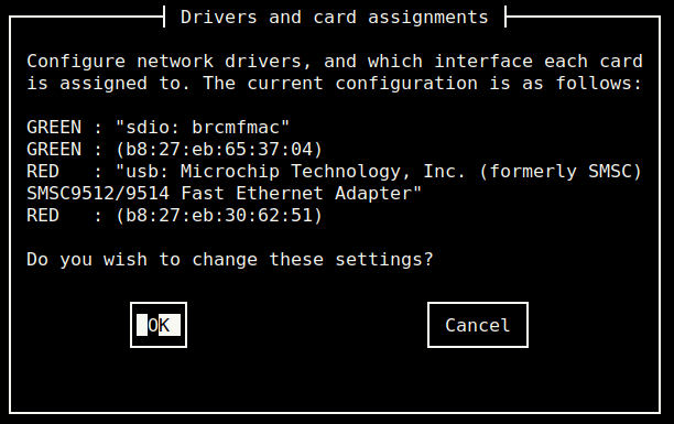
The “Drivers and card assignments” allows to map Raspberry Pi’s network cards to network interfaces. Map the Wireless card “sdio: brcmfmac” to the GREEN interface. “usb: SMSC9512/9514” should map to the RED interface.
For more information, please see https://wiki.ipfire.org/installation/step5.
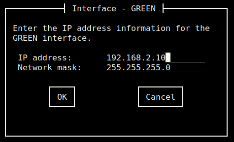
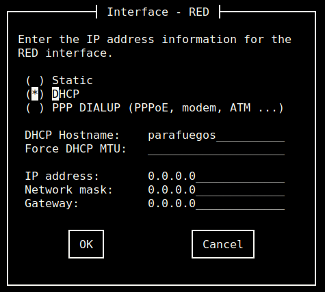
The “Address settings” can be used to configure the created network interfaces. Note that when configuring the “GREEN” interface a warning message will display, this is normal.
I’ve used “IP address” 192.168.2.10, and “Network mask” 255.255.255.0 for my setup.
For the RED interface, DHCP was used and all values were left as default.
Select “Ok” and then “Done” until the “DHCP server configuration” screen appears.
In this screen I’ve assigned IP values to “Start Address” 192.168.2.11, “End Address” 192.168.2.20 and “Primary DNS” I’ve used my ISP modem IP address, “Secondary DNS” 192.168.2.1.
Note the range 11 to 20 allows up to 19 hosts to be added on the network. If you require more hosts to be able to connect, then increase the values.
The message “Setup is complete” is displayed when the process is complete.
Enabling Wireless Access
Wireless access is disabled by default. In order to enable wireless, additional software needs to be installed and interface settings have to change to match the installation configuration settings.
Login with the root account and install “hostapd” application using the following command:
pakfire install hostapdThe hostapd.conf file by default uses the BLUE interface. As no BLUE interface was created, change it to use the GREEN one instead:
sed -i 's/interface=blue0/interface=green0/g' /etc/hostapd.confThe same applies to /etc/init.d/hostapd file, change the default interface from BLUE to GREEN:
sed -i 's/INTERFACE="blue0"/INTERFACE="green0"/g' /etc/init.d/hostapdIf necessary to customize the network name, change the ssid variable in /etc/hostapd.conf file.
The configuration file /etc/hostapd.conf comes with a default password set. Change “MY_PASSWORD” to your prefered password (this is the WiFi password used to access the network):
sed -i 's/wpa_passphrase=IPFire-2.x/wpa_passphrase=MY_PASSWORD/g' /etc/hostapd.confReboot the system for settings to take effect:
rebootIPFire Web interface
After the system finishes booting, connect to the WiFi network.
The web interface can be accessed through the URL https://192.168.1.1:444. Use your admin user details to login.
SSH Access
SSH configuration details can be accessed through the top bar navigation menu in “System” -> “SSH Access”:
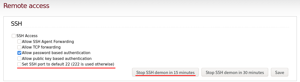
Instead of having SSH always enabled it’s best to allow temporary connections instead. Make sure “SSH Access” and “Set SSH port to default 22 (222) is used otherwise” options are unticked.
New SSH sessions can be enabled temporarily lasting for as long as 15 minutes using the “Stop SSH demon in 15 minutes” button. Only then connections through SSH are allowed.
DNS
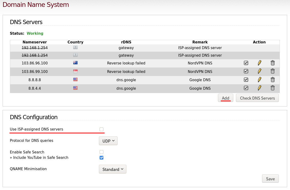
To prevent DNS leaks, ISP DNS should be disabled. Instead, use the VPN service provider or Google DNS server addresses. These details can be changed in “Network” -> “Domain Name System” web interface menu.
Untick the “Use ISP-assigned DNS Servers” option and add the DNS servers IPs list details to use with the “Add” button. Fill in the required details and make sure each entry is ticked in the list of IPs.
Please note, if necessary “Network” -> “DHCP Server” allows you to change the Primary DNS and Secondary DNS server IP addresses, in my case I’ve changed the IP addresses to the VPN provider DNS server IPs to prevent DNS leaks as unticking the “Use ISP-assigned DNS Servers” wasn’t affecting my connection and I was getting DNS leaks reported.
The VPN connection can be tested for DNS leaks using https://www.dnsleaktest.com/.
For reference, a list of public DNS servers is available in IPFire website.
WLanAP
Using “IPFire” -> “ WLanAP” allows you to configure the Raspberry Pi’s wireless access point.
If you see a 00 double entry in the “Country Code” setting, then change it other setting (this can become an issue if left unchanged. See bug https://bugzilla.ipfire.org/show_bug.cgi?id=12585#c18 for reference).
OpenVPN
Create an SSH connection session with the following command:
ssh root@192.168.1.1 -p 222Save your VPN authentication details in a file for automated authentication upon connecting to the VPN. Replace “USER_NAME” and “USER_PASSWORD” with your VPN account details and copy and paste into the SSH session terminal window:
mkdir -p /etc/openvpn && printf "USER_NAME\nUSER_PASSWORD\n" > /etc/openvpn/auth.conf && sudo chmod 600 /etc/openvpn/auth.conf
The following script allows to manage the VPN (I use NordVPN service, other providers should be similar but with a different download link – edit if necessary):
cat <<-'EOF' > "manage-vpn.sh"
#! /bin/bash

WORK_DIRECTORY="/etc/openvpn"
OVPN_SERVER_FILES="https://downloads.nordcdn.com/configs/archives/servers/ovpn.zip"

function main () {
	mkdir -p "$WORK_DIRECTORY"
	case $action in
	"--start")
		mkdir -p /dev/net
		mknod /dev/net/tun c 10 200
		chmod 600 /dev/net/tun
		openvpn --config "$WORK_DIRECTORY"/vpn.ovpn --auth-user-pass "$WORK_DIRECTORY"/auth.conf --auth-nocache --data-ciphers AES-256-CBC
	;;
	"--stop")
		if ([[ $(ps aux | grep "[o]penvpn" | wc -l) -eq 1 ]]) ; then
			killall openvpn
		else
			printf "* OpenVPN process is not running...\n"
		fi
	;;
	"--refresh-servers")
		mkdir -p "$WORK_DIRECTORY"/ovpn
		wget "$OVPN_SERVER_FILES" -P "$WORK_DIRECTORY"
		unzip -j -o "$WORK_DIRECTORY"/ovpn.zip -d "$WORK_DIRECTORY"/ovpn
		rm -r --interactive=never "$WORK_DIRECTORY"/ovpn.zip
        ;;
        "--status")
        	if ([[ $(ps aux | grep "[o]penvpn" | wc -l) -eq 1 ]]) ; then
			local pid=$(ps aux | grep "[o]penvpn" | awk '{print $2}')
			printf "* OpenVPN process is running with PID: $pid \n"
		else
			printf "* OpenVPN process is not running...\n"
        	fi
        ;;
        "--list-servers")
        	if [ -d "$WORK_DIRECTORY"/ovpn ]; then
        		ls "$WORK_DIRECTORY"/ovpn/ | less
        	else
        		printf "*** ERROR: - OVPN server files not found, use --refresh-servers. Exiting...\n"
			exit 127
        	fi
        ;;
        "--set-server")
        	if [[ "$#" -gt 1 ]]; then
        		if [ -f "$WORK_DIRECTORY"/ovpn/"$server" ]; then
        			ln -sf "$(realpath "$WORK_DIRECTORY")/ovpn/$server" "$WORK_DIRECTORY"/vpn.ovpn
			else
				printf "*** ERROR: - Invalid server name, use --list-servers. Exiting...\n"
				exit 127
			fi
		else
			printf "*** ERROR: - Missing server name, use --list-servers, if necessary --refresh-servers. Exiting...\n"
			exit 127
      		fi
        ;;
        "--show-server")
        	if [ -f "$WORK_DIRECTORY"/vpn.ovpn ]; then
        		stat "$WORK_DIRECTORY"/vpn.ovpn | head -1
        	else
			printf "*** ERROR: - A server hasn't been set, use --list-servers and then --set-server [SERVER_FILE_MAME]. Exiting...\n"
			exit 127
        	fi
        ;;
        *)
		printf "$0 - Option \"$action\" was not recognized...\n"
		printf "\n  * Work directory is set to $WORK_DIRECTORY\n"
		printf "\n  * Operations:\n"
		printf "    --start                         : Starts VPN\n"
		printf "    --stop                          : Stops VPN\n"
		printf "    --status                        : Get VPN process status\n"
		printf "\n  * VPN Operations:\n"
		printf "    --refresh-servers               : Downloads a new list of OVPN server files\n"
		printf "    --list-servers                  : Shows the list of available OVPN server files\n"
		printf "    --set-server [SERVER_FILE_NAME] : Sets the server to use for establishing VPN connections\n\n"
		printf "    --show-server                   : Shows the current set server\n\n"
		exit 127
        ;;
	esac
}

action=$1
server=$2

main $action $server
EOF
chmod +x manage-vpn.sh
Keep in mind that from time to time an updated list of servers should be downloaded for the most up-to-date ovpn configuration files. The script’s options:
- start : Starts VPN
- stop : Stops VPN
- status : Get VPN process status
- refresh-servers : Downloads a new list of OVPN server files
- list-servers : Shows the list of available OVPN server files
- set-server [SERVER_FILE_NAME] : Sets the server to use for establishing VPN connections
- show-server : Shows the current set server
Whenever necessary to change servers, enable SSH sessions from the Web Interface, login through ssh and re-create the symbolic link to point to a new ovpn file using the --refresh-servers option.
Firewall rule
Add the following IP Tables rule to /etc/sysconfig/firewall.local file, just below the line “##add your ‘start’ rules here”. Assuming you used the network IP details listed throughout the post, this rule will route all traffic from the 192.168.0.0/16 network through the VPN tunnel. In case you used different network IP details then change accordingly:
iptables -t nat -A POSTROUTING -s 192.168.0.0/16 -o tun0 -j MASQUERADEStarting OpenVPN
Execute the script manage-vpn.sh --start and if everything is working correctly, the message “Initialization Sequence Completed” is shown.
Finally, to make use of the VPN, connect a device through to the WiFi’s network (look for the ssid name). Once connected, public IP should match the chosen server IP address and not the public IP assigned by the ISP.
You can validate the IP and locations details by executing:
wget http://ipinfo.io/ -qO - The website https://ipleak.net/ can be used for verification.
Adding a firewall rule in the Gateway VM
To protect the network, add the following iptable rule to the Gateway guest VM:
sudo iptables -I OUTPUT -d 192.168.2.0/24 -j DROP && sudo bash -c "iptables-save > /etc/iptables/rules.v4"